Control flow analysis and graphing
27 Jul 2016, by mrexodiaToday’s post will be about control flow analysis and graphing, so read on if you are interested!
This blog is still looking for writers! See here for more information…
Introduction
At the moment x64dbg is only capable of showing disassembly in a linear fashion. Control flow can be somewhat inferred from jump arrows, but this can be a tedious and overwhelming process. This is one of the reasons we are interested in representing disassembly as a control flow graph. Another good reason is that x86 instructions can overlap and sometimes linear disassembly cannot show the full picture.
Analysis
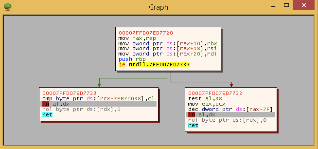
The first thing to look at is analysis of a function. We represent the function as a directed graph. The graph nodes are so-called basic blocks and the graph’s edges (arrows) are jumps in the disassembly. The function we will be looking at is shown below:
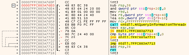
In this case a basic block is a block of instructions, that do not alter the control flow within the current function. We (falsely) assume that call instructions always return to the instruction after said call instruction so the control flow of the block is not interrupted. Additionally a basic block ends at a ret instruction (since that marks the end of the current function).
Since the function is (implicitly) represented as a graph we can use breadth first search (BFS) to traverse it. The algorithm implemented here combines the BFS with building the graph, which makes it quite compact and easy to understand (pseudocode):
analyze(entryPoint):
    graph = new Graph(entryPoint)
    queue = new Queue()
    visited = new Set()

    # Start at the entry point
    queue.enqueue(graph.entryPoint)

    # Traverse the graph
    while not queue.empty():
        # Check if we already visited this node
        start = queue.dequeue()
        if start == 0 || visited.contains(start):
            continue
        visited.insert(start)

        # Create a new node
        node = new Node()
        node.start = node.end = start

        # Disassemble the current basic block
        while true:
            instr = disassemble(node.end)
            if isBranch(instr) || isRet(instr):
                # Enqueue
                queue.enqueue(brtrue(instr))
                queue.enqueue(brfalse(instr))
                graph.AddNode(node)
                break
            node.end += instr.size
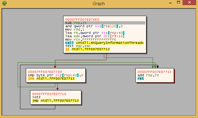
The functions brtrue and brfalse return the addresses of the destination blocks or zero. After running this analysis on the function the result looks something like this:
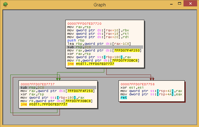
At the moment analysis is not working correctly. The analysis will have overlapping blocks if there are branches inside an existing block. It looks something like this (function is totally made up, don’t read too much into it):
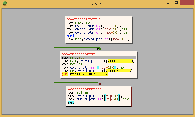
The first block should be split and a second pass easily solves this problem:
for node in nodes:
    addr = node.start
    size = disassemble(addr).size
    if graph.contains(addr + size):
        node.end = addr
        node.brtrue = addr + size
        node.brfalse = 0
        break
    addr += size
This splits the block correctly and inserts an extra edge between the nodes:
Now there are some remaining problems, like overlapping instructions, but those are fine the way it is in my opinion:
You can find the full code here if you are interested in the details.
GUI
Now the next part was showing the function graph in the GUI, there was quite an effort before doing this using OGDF, but this created various problems. Recently someone mentioned the Binary Ninja Prototype to me, so I decided to port that instead.
After about 7 hours of struggling with porting Python to C++, I ported the code and people seem to like the results :)
The details of the layout algorithm are beyond me and if you have any fixes, feel free to create a pull request!
Duncan